Voltage Follower
(Unity-Gain Buffer)
CIRCUIT
OP_FOLLOW1.CIR Download the SPICE file
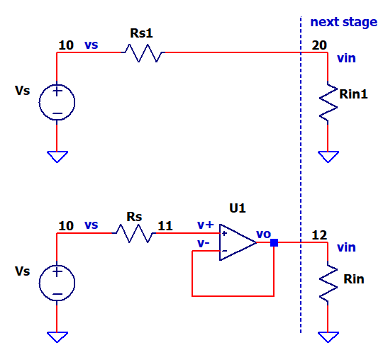
The simplest of all op amp circuits - the output connects directly to its neg input - creating a signal gain of 1 or unity.
So what is it good for? A common problem in analog design (see top circuit) occurs when a relatively high source resistance feeds a low input resistance of the next stage. This degrades the accuracy of measurement because Vs is reduced by the resistor divider action of Rs and Rin.
Vin = Vs * Rin/(Rs+Rin)
Vs - the sensor voltage or previous stage output to be measured
Rs - the source resistance of a sensor or amplifier
Rin - the input resistance of the next stage amplifier or ADC.
Vin - the measured voltage at the next stage amplifier or ADC.
VOLTAGE DIVIDER TROUBLES
How bad are things without the buffer / follower? The first circuit above shows the source (Vs, Rs) fed directly to the Rin of the next stage. As you can see, this forms a resistor divider action.
Vin = Vs * Rin1 / (Rs1 + Rin1)
For a sensor (Rs=1k) and next stage amplifier (Rin = 10k), the divider will significantly degrade your signal's accuracy!
CIRCUIT INSIGHT Run a TRAN simulation of OP_FOLLOW1.CIR with Vs=1V, Rs1=1k and Rin1=10k. Plot the results of the direct source to input connection by adding traces of V(10) and V(20). Yikes!!! How much of the signal was lost due to the Rs1 / Rin1 resistor divider?
Next, check how the buffer (Voltage Follower) of the second circuit above may have improved the accuracy. Open another plot window and add traces of the source V(10) and the buffered output V(12). Is the buffered output (V12) closer to the source V(10)?
HOW DOES BUFFERING HELP?
Here's a better circuit view including the internal op amp model.
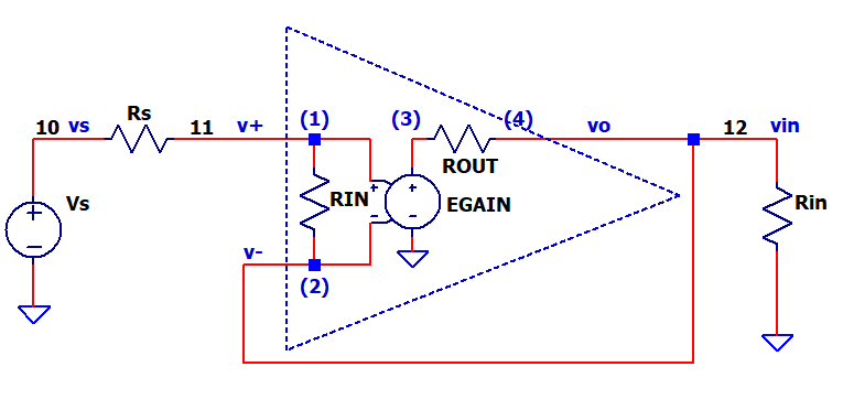
The voltage follower presents two desireable features to reduce voltage divider losses.
- Op Amp input resistance: Rinop = Super High ( >100M )
Kdivider = Rinop / ( Rs + Rinop ) ≈ 1
Negligable divider loss at buffer input! - Op Amp output resistance: Roop = Super Low
( <1 )
Kdivider = Rin / ( Roop + Rin ) ≈ 1
Negligable divider loss at buffer output!
The follower essentially isolates the higher source Rs from the lower Rin of the next stage.
Also, you may have noticed the op amp model has an ROUT=100 ohms. Well dang, doesn't that cause a divider loss too? Actually not so much! Why? Note that the output is fed back to the v- input after ROUT. Including ROUT inside the feedback point essentially makes the effective Ro of the op amp way lower than 100 ohms.
SIMULATION NOTE
The op amp is modelled using the OPAMP1 subcircuit. This uber simple model (RIN, EGAIN, ROUT) helps illuminate some cool fundamentals without a number of other distracting components.
SPICE FILE
Download the file or copy this netlist into a text file with the *.cir extention.
OP_FOLLOW1.CIR - OP AMP VOLTAGE FOLLOWER
* UNITY-GAIN BUFFER
*
VS	10	0	PWL(0us 0V 10us 1V)
*
* SOURCE WITH NO BUFFER TO RIN
RS1  10	20	1K
RIN1 20	0	10K
*
* SOURCE WITH BUFFER BETWEEN RS AND RIN
RS	10	11	1K
XOP 11  12  12   OPAMP1
RIN	12	0	100K

*
* OPAMP MACRO MODEL, SINGLE-POLE
* connections:      non-inverting input
*                   |   inverting input
*                   |   |   output
*                   |   |   |
.SUBCKT OPAMP1      1   2   4
* INPUT IMPEDANCE
RIN	1	2	10MEG
* DC GAIN
EGAIN	3 0	1 2	100K
ROUT	3	4	100
.ENDS
*
* ANALYSIS
.TRAN 	100US
* VIEW RESULTS
.PROBE
.END