Op Amp - Basic Diode Limiter
CIRCUIT
OP_LIMITER0.CIR Download the SPICE file
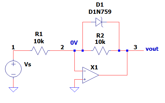
In addition to Rs and Cs, the Diode can play a key role in op amp circuits creating interesting and useful non-linear circuits. For example, the simple circuit above can implement a basic limiter, rectifier and sine-to-sqware wave converter. How is this done?
HOW IT WORKS
Here's a simple approach to understanding the operation - think of the circuit as two functions.
1. The Amplifier fuction - how does the inverting amplifier work without the diode present?
2. The Diode function - how does the diode limit the voltage across R2?
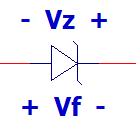
The zener diode conducts in both polarities:
Vf - forward
voltage direction (<0.65V)
Vz - reverse voltage direction (zener voltage).
INVERTING AMPLIFIER
CIRCUIT INSIGHT Run a TRAN simulation of OP_FOLLOW1.CIR. Set Vs=10Vpeak, R1=10k and R2=10k. Remove the zener diode D1 by commenting it out with a "*" in front of its line.
*D1 2 3 D1N759
What do you expect to see at the output? The gain of the inverting amp is
Vo = Vin * -R2/R1 = 10Vpeak * 10k/-10k = 10Vp * -1
Plot the input V(1) and output V(3). Do you see the input along an inverted version at the output?
RECTIFIER
Now place the diode (12V Zener) back in the circuit by removing the "*" in front of D1. What do you expect to see at the output?
- Positive Cycle
- the +10V across R2 is less than the D1 Zener Voltage (Vz=12V)
- D1 does not conduct - normal inverting operation.
- Negative Cycle
- the -10V across R2 is greater than D1 Forward Voltage (Vf=0.65V or less)
- D1 conducts forward - output clipped at -Vf.
The rectifier function has been acheived! For this simple circuit, the negative cycle is clamped to a small negative voltage. More precise rectifier designs can clip the negative cycle to 0V. (See Op Amp Limiter.)
VOLTAGE LIMITER
Now run a TRAN simulation with Vs=20Vpeak. What do you expect to see at the output?
- Positive Cycle
- the +20V across R2 is greater than the D1 Zener Voltage (Vz=12V)
- D1 conducts reverse - output clipped at +12V.
- Negative Cycle
- the -20V across R2 is greater than D1 Forward Voltage (Vf=0.65 or less)
- D1 conducts forward - output clipped at -Vf.
Try reversing the diode.
Try a different Zener diode!
Try adding another zener D2 in series with
D1.
D1 2 4 D1N759
D2
3 4 D1N759
Can you predict the output waveform?
SINE-TO-SQUARE WAVE CONVERTER
This last function is easy to acheive - simply make R2 larger to increase the inverting gain.
The larger the gain (and sinewave across R2), the faster Vout will reach the diode's forward or reverse (zener) conduction voltage. With R2 very large, the output begins to look like a square wave.
SPICE FILE
Download the file or copy this netlist into a text file with the *.cir extention.
OP_LIMITER0.CIR - BASIC DIODE LIMITER
*
VS	1	0	SIN(0VDC 10VPEAK 1KHZ)
*
* INVERTING AMPLIFIER
R1	1	2	10K
R2	2	3	10K
* DIODE LIMITING
*D1	2	3	D1N759
* OP AMP
XOP1	0 2	3	OPAMP1
*
*
* ZENER DIODES
.model D1N746 D(Is=5u Rs=14 Bv=2.81 Ibv=5u)
.model D1N752 D(Is=0.5u Rs=6 Bv=5.20 Ibv=0.5u)
.model D1N758 D(Is=0.05u Rs=9 Bv=9.49 Ibv=0.05u)
.model D1N759 D(Is=0.05u Rs=12 Bv=12.0 Ibv=0.05u)
*
*
* OPAMP MACRO MODEL, SINGLE-POLE
* connections:      non-inverting input
*                   |   inverting input
*                   |   |   output
*                   |   |   |
.SUBCKT OPAMP1      1   2   6
* INPUT IMPEDANCE
RIN	1	2	10MEG
* DCGAIN =100K AND POLE1=100HZ
* GBP = DCGAIN X POLE1 = 10MHZ
EGAIN	3 0	1 2	100K
RP1	3	4	1000
CP1	4	0	1.5915UF
* OUTPUT BUFFER AND RESISTANCE
EBUFFER	5 0	4 0	1
ROUT	5	6	10
.ENDS
*
*
* ANALYSIS
.TRAN 	10US  1000US
.PROBE
.END