Ultra-Lite Digital SMU
Part 2 - Hardware Prototype using an Arduino
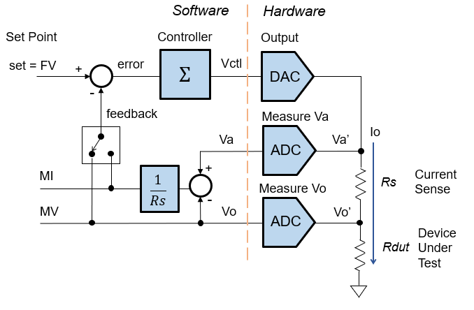
Let's build an ultra-lite SMU to learn digital control. Why? A small system provides an easy on-ramp to grasp bigger
ideas without getting lost in a myriad of circuit details. Later,
you can develop more complex SMU's on a solid foundation.
Part 1 - describes the essential
blocks of a digital SMU (with SPICE file).
Part 2 - builds a prototype with the Arduino and a just few components.
Back to SMU Series
SMU SPECIFICATIONS
- Force Voltage: 0 to +4V
- Force Current: 0 to +5mA
- Current Sense
- Resistor: Rs = 100 ohms
- Voltage: Vs = 5mA*100 ohms = 0.5V max
SCHEMATIC
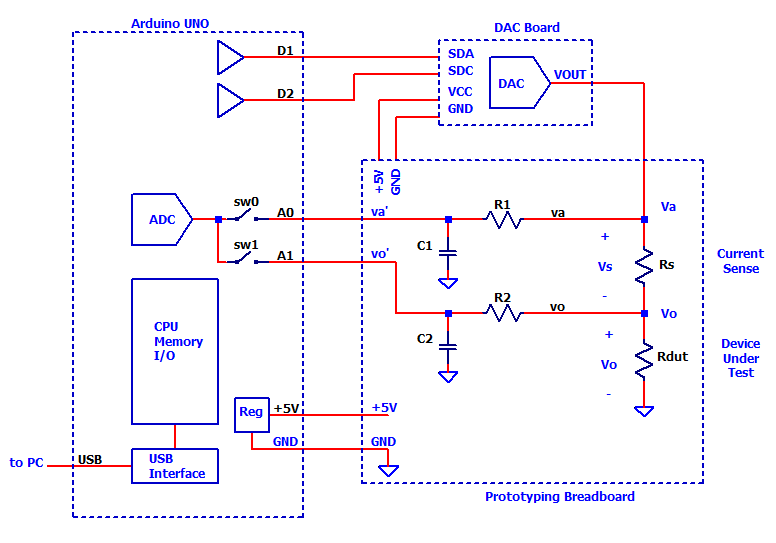
Here's the schematic of our SMU showing connections between the Solderless Breadboard, a DAC board and the Arduino UNO Board.
CIRCUIT NOTES
- The block diagram above shows 2 ADCs. However, the Arduino achieves a similar function with a single DAC and switches for inputs A0 and A1.
- An external DAC board acheives and higher resolution and faster response than the Arduinos PWM output.
- Each analog input (A0,A1) has an RC low-pass filter to reduce noise and provide a low-Z source to drive the ADC's Sample and Hold capacitor.
PROTOTYPE
There is no easier way to prototype a circuit than with the Solderless
Protoboards. Drop in a component and begin wiring! You can easily test, modify and
experiment with your design.
A handy online drawing program
(www.cirkitstudio.com/) allows you to create a parts-based wiring diagram as
shown below.
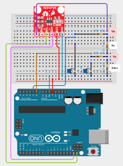
Please note, the diagram above is only a suggestion. Arrange parts and wire the circuit anyway you prefer!
PARTS LIST
Even with the most basic components, you can build a working SMU. Feel free to select alternate components for preference / availability / cost.
Qty
(Ref)Description Part Number
(Digikey option)1 Arduino Uno Rev3 Microcontroller Board A000066 1 USB Cable Type A/B generic 1 DAC Breakout Board, 12-Bit, I2C Interface MCP4725 (Sparkfun) 1 Solderless Breadboard, SparkFun Electronics PRT-12002 (1568-PRT-12002-ND) 1 pkg Jumper Wires, Various Lengths, M to M, Adafruit Industries (1528-2185-ND) 2
(R1,R2)RES 100K OHM ≤5% any available 1
(C1,C2)CAP CER 1nF X7R any available 5
(Rs)RES 100,1K,10k,100k,1M OHM ≤1%
(Various values for different ranges)any available
FLOW CHART
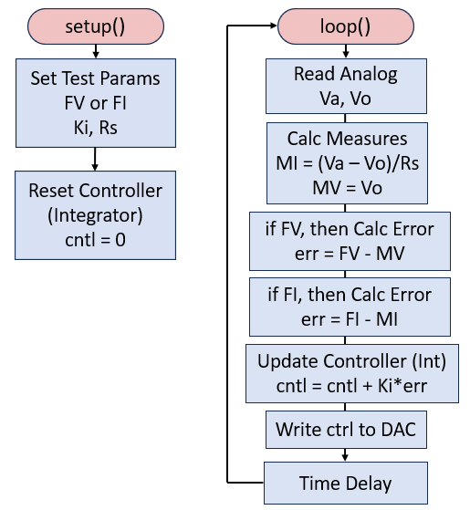
The overall code blocks for the SMU is fairly straightforward.
ARDUINO BASICS
Here's the fast track version of running a C program (sketch) on your Arduino Board.
- Open the Arduino IDE Software
https://www.arduino.cc/en/software - Connect UNO Board to your computer
https://docs.arduino.cc/hardware/uno-rev3/ - Select Board Name
Select UNO from drop down menu. - Download program (Right-Click "Save link as...")
SMU1-dig-lite-basic-1.ino - Open program (sketch) in IDE
SMU1-dig-lite-basic-1.ino - Click Compile Button
Generates executable code, checks for errors. - Click the Upload Button
Upoads compiled code into UNO and begins running. - Click the Serial Monitor
Window displays output from PrintSerial statement.
THE CODE
The program is straighforward, many examples have been published for writing the DAC and reading the ADC inputs.
DAC Code
We need to add the Wire library for the MPC4725 DAC board and set its address.

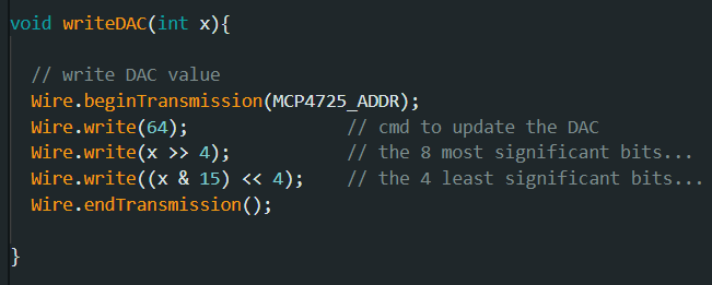
The writeDAC function handles the low levels details of writing an integer value into the 12-bit DAC registers.
Setup()
This code excecutes once in the Arduino Sketch.
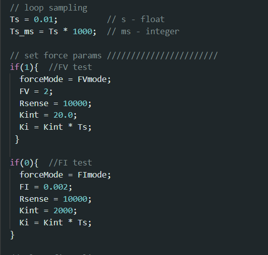
The code sets up the SMU test.
- Ts - sets the sampling interval.
- Select FV or FI mode by forcemode = FVmode or FImode.
- FV Test - enabled by if(1), sets FV mode, force value FV=4 (V), integrator gain Kint, calculates actual Ki via Ts.
- FI Test - disabled by if(0), sets FI mode, force value FI=0.002 (A), integrator gain Kint, calculates actual Ki via Ts.
Loop()
This code runs continuously. The main SMU controll loop code simply follows the flow chart above.
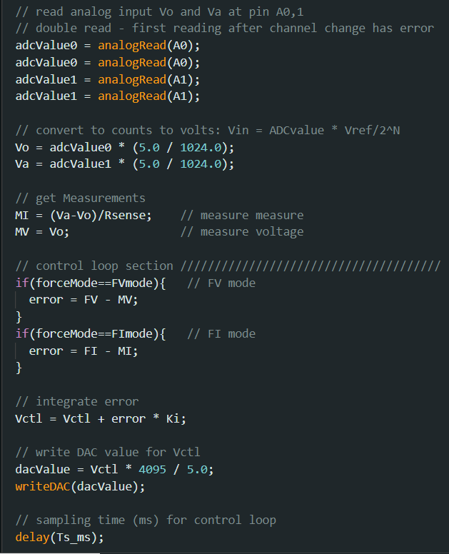
The code above implements the control loop functions.
- Analog channels are read twice. Why? The first read after channel change typically has an error.
- ADC readings are converted to analog voltages using scaling factor 5V / 1024 counts.
- Output current found as Io = (Va-Vo)/Rs.
- Error calculated for either FV or FI mode.
- Error is integrated (running sum) using simple equation: vctl = vctl + error * KI.
- Integrator output vctl gets converted to equivalent 12-bit DAC value using scaling of 4096 / 5V.
- DAC function gets called to pass 12-bit value to DAC board.
- FInally, a time delay updates the control equations every Ts seconds. (Of course this assumes the code's running time code is negligable compared to the 10ms.)
Display Result and Averaging
This code displays all the SMU measuments every 250 ms on your computer screen. The variable testTime keeps track of the time (ms) since the program started.
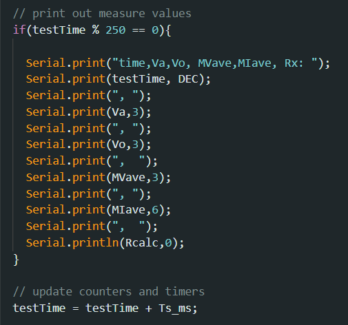
Because the measurements may be noisy, we'll apply a running average to the readings.
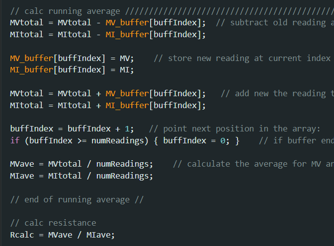
The code implements a circular buffer that subracts the oldest value and adds the newest value. The average is simply the sum total of the buffer divided by the number of readings in the buffer.
Finally! We'll calculate the resistance measurement from the averaged values Rcalc = MVave / MIave.
FV TEST
What can we test even though the analog circuitry has NOT been prototyped? Good news! We can jumper the Arduino's 3.3V supply directly into the A0 analog input.
- Insert jumper wire from 3.3V Socket to the A0 Socket.
- Open program (sketch)
DVM1_initial_test1.ino - Edit statement in setup():
Vrange=0 (4V range) - Click the Upload Button
Also Compiles before uploading. - Click the Serial Monitor
- Does the reading show about 3.3V?
if Yes, then celebrate the success!
if NO, then check code and jumper.
Back to SMU Series