|
RESISTOR
DIVIDER
SIGNAL ATTENUATION
This is a simple
example of using VBA for electronic design
EE_Resistor_Divider.xlsm
. You could ask - why use a
VBA function at all? But, even in this case, VBA makes analysis a little
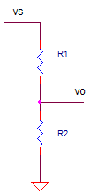
easier to explore. Here's the divider circuit.

The gain (or, attenuation) of
this circuit is given by
K = R2 / (R1 + R2)
Let's create a simple VBA function to perform
this calculation (See VBA Basics).
| |
Function
K_Rdiv1(R1, R2)
' Gain of resistor divider
K_Rdiv1 = R2
/ (R2 + R1)
End Function |
To see the VBA code hit ALT-F11
and double click on the Modules > Module1 in the VBA Project window. This
opens the code window for this module.
DIVIDER ACCURACY
For this example, the divider is creating a precision
+5V reference from an available +10V reference. The +5V level is used as a reference
voltage for an ADC. But how accurate is this +5V level? Let's calculate the
output given ideal components and then given initial tolerances of the
+10V and resistors R1 and R2.
|
Vs |
R1 |
R2 |
K Rdiv |
Vo |
Vo_err |
Error (%) |
|
|
|
10.0 |
10000 |
10000 |
0.500 |
5.000 |
0.000 |
0.0 |
Ideal output |
|
10.0 |
10100 |
10000 |
0.498 |
4.975 |
-0.025 |
-0.5 |
1% error in R1 |
|
10.0 |
10000 |
10100 |
0.502 |
5.025 |
0.025 |
0.5 |
1% error in R2 |
|
10.1 |
10000 |
10000 |
0.500 |
5.050 |
0.050 |
1.0 |
1% error in Vs |
The cells in the K_Rdiv column hold the
function call. For example, in the first entry in the K_Rdiv column looks
like
=K_Rdiv1(C11,D11)
where C11 and D11 hold R1 and R2. Vo
calculates the output as
vo = K_Rdiv * vs
And finally we calculate the error from the
ideal result in both voltage and %.
The first row above, tells us the ideal story
we want to believe. With ideal resistors R1=R2=10k you get a gain of 0.500
and vo = 5.000V. But what happens if you place real resistors with an
initial 1% tolerance in the circuit? The entry for a 1% error for R1 was
typed in the second row as 10000*1.01. What kind of error did it produce?
This resulted in a 0.5% error. You can also see the influence of errors for
R2 and vs. Interesting how the resistors error effects the output by half
their tolerance. On the other hand the voltage va sources error effects the
output directly by its tolerance.
You can down load the
spreadsheet EE_Resistor_Divider.xls
TRY IT!
The best part of VBA is that it lets you play
with the code. Once you see some code, jump right in and start messing with
it or write a new function altogether. Just copy the existing code to a
space just below the original. Then start modifying the name and
calculations. Here are a few ideas you can try:
- Write a function to
calculate the parallel combo of two resistors. You can name the function
something like "Function R_Par(R1, R2)".
- Make a function to
calculate the non-inverting gain of an op amp.
Back to Topics
|
![]() Electronic Design with Excel
Electronic Design with Excel