Case Study:
Which Amplifier has Lower Errors?
Non-Inverting vs. Inverting Op Amp!
Suppose you had the choice between two amplifiers for a precision front-end design:
- Non-Inverting (K = +2)
- Inverting (K = -2)
Which provides better DC accuracy?
Design Challenge: A sensor can be wired for either polarity (+2V or -2V full-scale). The sensor's signal must be scaled to the input range of an ADC (+4V full scale). We'll perform an error analysis for each amplifier. For the same magnitude in gain
- which amp has lower Sensitivies / Errors?
- which amp performs better in Offset or Gain Errors (or both?)
Get a refresh of the Non-Inverting and Inverting Op Amp.
For tutorials and other examples, goto EBA Series.
OFFSET AND GAIN ERRORS
What are the Offset and Gain Errors of a basic amplifier block?

- Ideal Amplifier with Gain K
- Vo = Vin*K
- Actual Amplifier with errors
- Vo = Vin* (K+∆K) + ∆Voffset
- ∆K - Gain Error
- change in Gain from ideal (K).
- also called Slope, Span error
- ∆Voffset - Offset Error
- change in offset from ideal (0V)
- also called Intercept, Zero Error
- Combined Offset and Gain Errors
- Error = ±∆Voffset + ( ±∆K x Reading )
AMPLIFIERS
Schematics with Error Sources
Non-inverting and Inverting Amps with errors.
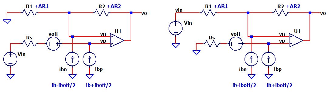
Error Sources
To compare designs, we'll focus on the following initial errors.
Description Initial OFFSET ERRORS voff, Input Offset Voltage
ib, Input Bias Current1 mV
100 nAGAIN ERRORS R2_Tol, Resistor Tolerance
R1_Tol, Resistor Tolerance1.0 %
1.0 %
Conditions and Assumptions
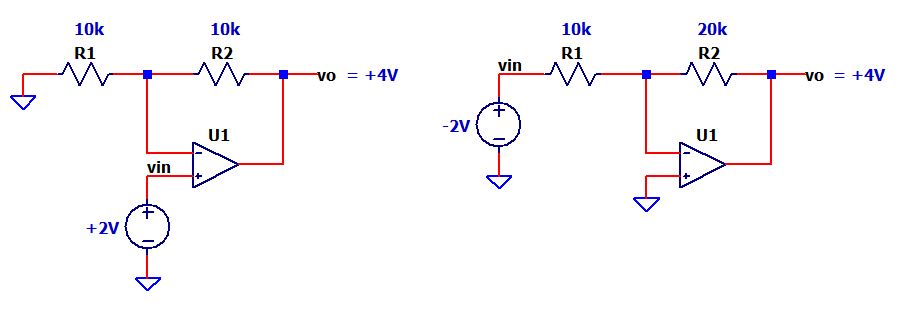
Non-Inverting Amplifier
- R1=10k, R2=10k, Rs = 0
- K = R2/R1+1 = +2 V/V
- Vin = +2V, Vo = +4V
Inverting Amplifier
- R1=10k, R2=20k, Rs = 0
- K = -R2/R1 = -2 V/V
- Vin = -2V, Vo = +4V
Temperature
- Ambient: Ta = 25C
- Max change: ∆T = 30C
Design Constraints
- Low Power - No resistors below 10k
OFFSET AND GAIN ERRORS
Let's walk through the error analysis for both amplifiers. For each error we'll show
- S - The Sensitivity of vo to the error source.
- ∆Voffset, ∆K/K - The Offset or Gain Error at the output vo.
| Description | Non-Inv Amplifier | Inverting Amplifier |
| Resistors Signal Gain |
R1=10k, R2=10k K = vo/vin = R2/R1+1 = +2 |
R1=10k, R2=20k K = vo/vin = -R2/R1 = -2 |
| OFFSET ERRORS | ||
| Input Offset Voltage Input Bias Current |
voff = 1mV S = ∆vo/∆voff = R2/R1+1 = +2 ∆Voffset = voff * S = 1mV * 2 = 2mV ib = 100 nA S = ∆vo/∆ib = -R2 = -10k ∆Voffset = ib * S = 100 nA * 10k = 1mV |
voff = 1mV S = ∆vo/∆voff = R2/R1+1 = +3 ∆Voffset = voff * S = 1mV * 3 = 3 mV ib = 100 nA S = ∆vo/∆ib = -R2 = -20k ∆Voffset = ib * S = 100 nA * 20k = 2mV |
| GAIN ERRORS | ||
| Resistor R1 Resistor R2 |
R1_Tol = 1% S = (∆K/K) / (∆R1/R1) = -0.5 (see Excel file calc) ∆K/K = R1_Tol * S = 1% * -0.5 = -0.5% R2_Tol = 1% S = (∆K/K) / (∆R2/R2) = +0.5 (see Excel file calc) ∆K/K = R2_Tol * S = 1% * 0.5 = 0.5% |
R1_Tol = 1% S = (∆K/K) / (∆R1/R1) = -1.0 (see Excel file calc) ∆K/K = R1_Tol * S = 1% * -1.0 = -1.0% R2_Tol = 1% S = (∆K/K) / (∆R2/R2) = +1.0 (see Excel file calc) ∆K/K = R2_Tol * S = 1% * 1.0 = 1.0% |
SHOWDOWN SUMMARY
Which configuration performed better (lower errors)? The clear WINNER for this design showdown is the Non-Invering Amplifier!
Why? You've likely noticed the Non-Inverting had lower Sensitivities (1.5x to 2x lower) for both the Offset and Gain Errors. To understand better, a question is posed.
Question: Which amplifier config appears below?
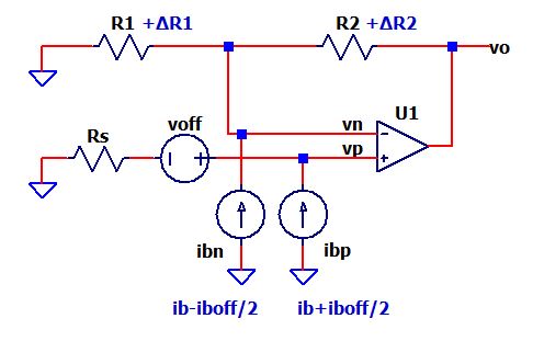
Answer: BOTH!
- By setting Vin = 0V, the two circuits reduce to the common schematic above.
- The error equations are the same for both!
So what's different?
- For the Non-Inverting: R2=10k. But notice for the Inverting: R2=20k.
- A HIGHER R2 value (and R2/R1 ratio) for the Inverting Amp produces HIGHER Offset Sensitivities and Errors (bad news).
What about Gains?
- Observe that the Non-Inverting Gain (R2/R1+1) includes a "+1" term. The added term generally reduces the Sensitivity for R1 and R2 to less than 1.0.
- However, the Inverting gain (-R2/R1) show R1 and R2 as direct multipliers. This means that the Sensitivity magnitudes are equal to 1.0.
WHAT ABOUT LARGER GAINS (>10)?
What happens to the error showdown between higher gain ampifiers?
Suppose the desired gain magnitude is +10 V/V for the Non-Inverting (R2=100k) and -10 V/V for the Inverting (R2=110k). You can discover the error results by entering your new values for R2 in the Excel spreadsheet (see link below).
WHAT ABOUT OTHER ERRORS?
For higher precision designs, you might consider additional error parameters (Aol, CMRR, PSRR)! In some cases, the Inverting Amplifier has an advantage! Look for these errors treated in future topics.
EXCEL FILE
Explore the hands-on spreadsheet! Compare the Sensitivities between the two amps highlighted in RED.
- Excel file: amp1-non-vs-inv-study-1.xlsx
Right Click on the filename, select "Save link as...". - Open file, explore the Calc, Offset and Gain Sheets
- Play in the sandbox, modify values, see the impact on errors.
- Copy to a new file - experiment!
TRY IT!
- Suppose the required gain magnitude is 10x for both amplifiers. Enter R2 = 100k for the Non-Inverting and R2=110k for the Inverting config.
- Is there a clear winner showing signficantly lower errors?
For tutorials and other examples, goto EBA Series