COMPONENT TOLERANCES AND
TEMPCOS
PART I
CIRCUIT
R_DIVIDER.CIR Download the SPICE file
Your design team has called on you to generate a 1
± 0.010 VDC reference voltage from an
existing
+2.5 V reference. No problem, a resistor divider, 1.5 kΩ
and 1.0 kΩ, will work fine. Although, you can order resistor
values like 1 kΩ, the
truth is that one doesn't really exist. What you'll end up with is a
resistor that's close to 1 kΩ, like
1003.4 Ω, 998.1 Ω, and so on.
While the manufacturer is kind enough to tell you how far
off the actual value can be (±1% for example), the question is this: will
your reference fall in or out of spec? How can you calculate the worst case
error? There's several ways to do it, each one has it own advantages.
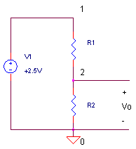
RESISTOR DIVIDER
Not the most glamorous circuit, but the resistor divider lends itself intuitively for the study of component variations. The divider creates an output voltage
Vo = V1 ∙ R2 / (R1 + R2)
Unfortunately the resistors can have actual values of
R1 + ΔR1
R2 + ΔR2
where ΔR1 and ΔR2 represent the errors based on tolerances (TOL)
ΔR1 = R1 ∙ TOL
ΔR2 = R2 ∙ TOL
or errors based on temperature coefficients (TEMPCO)
ΔR1 = R1 ∙ TEMPCO
∙ ΔT
ΔR2 = R2 ∙ TEMPCO ∙ ΔT
which can produce a non-ideal output voltage, for example from R1.
Vo' = V1 ∙ R2 / (R1+ΔR1 + R2)
resulting in a voltage error
ΔVo = Vo' - Vo
Our ultimate goal is to find the worst case error ΔVo_tot, given all of the component variations in the circuit. The first method gets us there, but not very efficiently.
METHOD 1 - PLUG AND CHUG WITH SPICE
If you've chosen ±1% resistors, ΔR represents the initial tolerance
ΔR1 = R1 ∙ TOL = 1500 Ω ∙ ±0.01 = ±15 Ω
ΔR2 = R2 ∙ TOL = 1000 Ω ∙ ±0.01 = ±10 Ω
With this method you simply try all the variations and combinations of resistances where ΔR can be +1%, 0% or -1% of the desired value.
CIRCUIT INSIGHT
Run a simulation of R_DIVIDER.CIR,
varying R1 and R2, then checking the bias point solution in the *.OUT file.
The SPICE file also runs a Transient Analysis so you can plot
V(2)
with a cursor to get a quick read on the value. Your findings should be
similar to the table below.
| Trial | R1 + ΔR1 | R2 + ΔR2 |
Output Vo' |
Error ΔVo |
|
| 1 | 1515 | 1000 | 0.994 | -0.006 | |
| 2 | 1485 | 1000 | 1.006 | +0.006 | |
| 3 | 1500 | 1010 | 1.006 | +0.006 | |
| 4 | 1500 | 990 | 0.994 | -0.006 | |
| 5 | 1515 | 1010 | 1.0000 | 0.0 | |
| 6 | 1515 | 990 | 0.988 | -0.012 | |
| 7 | 1485 | 1010 | 1.012 | +0.012 | |
| 8 | 1485 | 990 | 1.0000 | 0.0 |
A bit of work here, but interesting to see the effects! What happened when R1 was increased or decreased? Also note, increasing or decreasing resistors of the same tolerance produces the same magnitude of error. What combination gave the worst case error? And further, we notices that the magnitude of the worst case error ΔVo (Trials 6 and 7) appears to be sum of the magnitudes of the individual resistor errors (Trials 1 or 2 and 3 or 4).
ΔVo_tot = 0.012 = 0.006 + 0.006
Also interesting - what happened when both R1 and R2 go up or down? There's no effect on the output voltage. Why? In these cases the resistor ratio essentially stayed the same.
Does the divider meet the spec of 1 ± 0.010 V given all of the resistor combinations that might be installed on the factory floor? Unfortunately, no. But there's better resistors available.
HANDS-ON DESIGN What is the max error for resistors with 0.5% or 0.1% tolerances? Run a few SPICE simulations to fins out. What happens to the individual and sum of errors when you mix tolerances, say 5% for R1 and 1% for R2?
DC SENSITIVITIES
Our experiment above answered an important question: how sensitive is the output voltage to changes in R1 or R2? From trials 1 and 3 you could calculate the sensitivity in V per Ω as the ratio of the voltage change to the resistance change.
ΔVo / ΔR1 = - 0.006 V / 15 Ω
= - 0.0004 V/ΩΔVo / ΔR2 = + 0.006 V / 10 Ω
= + 0.0006 V/Ω
What are these sensitivities good for? Now you can approximate the voltage change ΔVo given any resistance change ΔR'.
ΔVo = (ΔVo/ΔR) ∙ ΔR'
Well, not quite any resistance change. But, the approximation is a good one for resistance changes that are relatively small, several percent or so. Accurate enough for most circuit applications.
PART II
Are there other ways to calculate DC sensitivities? In Part II, you'll get a chance to use some calculus (Method 2) to find some answers. Finally, we'll request SPICE (Method 3) to do the job for us.
TEMPCOS
The above table could have been generated for temperature coefficients where ΔR represents the total resistance change over some temperature ΔT. For example, if you specified a resistor with a tempco of ±100 ppm/°C, the ΔR over a ΔT = 10 °C change would be
ΔR1 = R1 ∙ TEMPCO ∙ ΔT
= 1500 Ω ∙ ±100/106 °C-1 ∙ 10 °C
= ±1.5 Ω
ΔR2 = R2 ∙ TEMPCO ∙ ΔT
= 1000 Ω ∙ ±100/106 °C-1 ∙ 10 °C
= ±1.0 Ω
FINAL NOTE
Keeping our focus on the resistors, we assumed that the +2.500 VDC input voltage was without error. Of course in the real world it will have its own tolerance. By varying V1 to find its effect on Vo, you can include it in your overall error budget.
Also, this topic explores sensitivities of DC voltage levels. AC and transient sensitivities are other topics all together.
See Part II for a chance to use some calculus and SPICE to find the same sensitivities.
SPICE FILE
Download the file or copy this netlist into a text file with the *.cir extension.
R_DIVIDER.CIR - FIND COMPONENT SENSITIVITY
*
V1	1	0	DC	2.5V
R1	1	2	1500
R2	2	0	1000
*
* ANALYSIS
.TRAN 1MS 10MS
*.SENS V(2)
*
* VIEW RESULTS
.PROBE
.END
© 2005 eCircuit Center