AC to DC Converter
CIRCUIT

DMM_R_MEAS1.CIR
Download
the SPICE file
When you turn the big rotary switch on a DMM to AC Volts, you'll notice a couple
of things.
1. Placing the leads across a battery (DC voltage) will produce a
reading of zero volts.
2. Sticking the leads into an AC outlet will produce
a reading of about 120V.
So I asked myself - what compact little circuit blocks DC
and measures the AC signal?
At the heart of the AC-to-DC converter lies a classic crcuit from the instrumentation playbook: a precision rectifier. The rectifier is needed because a DC meter (dual slope converter) produces an average reading of the input. An AC waveform, however, has an average value of 0. The solution requires converting the AC waveform to one that has a non-zero average.
PRECISION RECTIFIER
The rectifier simply passes the positive portion, while removing the negative portion. This creates a non-zero average of the input signal. Although the circuit above looks a bit complex, it's really based on the AC coupled inverting amplifier. To wrap our brains around the operation, you can redraw the rectifier as three separate circuits reflecting the behavior at three operating conditions: postive AC cyle, negative AC cyle, and DC.
POSITIVE OUTPUT CYCLE
During the positive portion of the output waveform, the following components
swing into action..

Where is the actual output of the circuit above? The inverting config
accurately creates a voltage of
vo = vs x -R2/R1
at D1's cathode. What about the voltage across D1? It
get's absorbed in the open loop as the amplifier works to make the gain
happen around the R2 & R1 components. Although R3 has no function during the
positive output cycle, it keeps the node at 0V during the negative output
cycle when D1 is OFF.
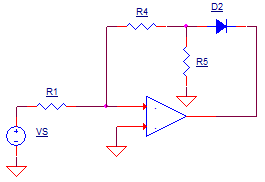
NEGATIVE OUTPUT CYCLE
During the negative output, these components swing into action..

Similarly, the inverting config accurately creates a voltage of
vo = vs x -R4/R1
this time at D1's anode.
0V OUTPUT
For DC inputs where no AC is present, C1 is essentially open. Under this
condition the output needs to be an accurate 0V. However, this presents a
problem because neither D1 or D2 are conducting. To provide a DC feedback
path, RDC1 and RDC1 were added. These two components create a unity- gain
buffer with the positive input grounded.

Although useful at DC, RDC1 and RDC1 needed to be removed for AC signals. Capacitor CDC1 accomplishes this by shorting out this feedback path at higher frequencies.
LOW-PASS FILTER
PROBLEM: The recitifier creates a waveform with a non-zero average - essential for measurement by the dual-slope Analog-to-Digital-Converter (ADC). However, for highest accuracy, we need to present the ADC with a steady DC level. SOLUTION: Add a simple low-pass filter - RDC1, CDC1, RDC2 and CDC2. The required time constant of the RC filter needs to be long enough to convert the input's positive half cycles to a nice steady level.
TEST IT
We'll test our rectifier / filter combo with 1V peak 60 Hz input.
To design a unity-gain inverting rectifier, make R1=R2=R4=10k. Theis
makes the amplifier gain at each half-cycle equal to
K = -R2/R1 = -R4/R1
= -1 V/V.
Please note, the RC filter takes some time to settle to it's final value. Luckily, the Transient Analysis command comes with a handy feature that lets you throw away simulation results up to a specific delay time. For example, the statement
.TRAN 10US 1000MS 900MS
simulates the circuit to until 1000 ms, but discards the data before 900 ms.
To accomplish the rectifying feat, the op amp has to compensate for the diode drop for each of the half cycle. To see this in action, plot the amplifiers output at V(4). As you can see, the amplifier needs some speed when the AC waveform flips polarity and the output must swing quickly from -0.7V to +0.7V.
Finally, to see the low-pass filter output, view V(9) along with the rectified output V(5) together in another plot pane. You may have noticed the filtered output is not the same value as the peak, or even RMS value of the input! Why? We've produced an average of the waveform, not the RMS value. However, you can give the amplifier some gain via R2 and R4 to make the reading appear to calculate the RMS value.
At some frequency, the op amp runs out of gas and the rectified waveforms don't look so pretty any more. For example, try running the recifier with input frequencies of 600Hz and 6000Hz. (Set the time to discard data 990ms and 999ms, respectively.) What happened to the waveform at V(5)?
SPICE FILE
DMM_AC_TO_DC1.CIR
*
* INPUT VOLTAGE
VIN	1	0	SIN(0V 1V 60HZ)
*
* RC INPUT
C1	1	2	10UF
R1	2	3	10k
*
* AMP AND DC FEEDBACK
XOP1	0 3 4	OPAMP1
RDC1	3	7	10K
CDC1	7	0	10UF
RDC2	7	4	10K
* POS CYCLE
R2		3	5	10K
R3		5	0	2K
D1		4	5	D1N4148
*
*  NEG CYCLE
R4		3	6	10K
R5		6	0	2K
D2		6	4	D1N4148
*
* LOW PASS FILTER
RLP1	5	8	100K
CLP1	0	0	1UF
RLP2	8	9	100K
CLP2	9	0	1UF

*
* DIODE
.model	D1N4148	D(Is=0.1p Rs=16 CJO=2p Tt=12n Bv=100 Ibv=0.1p)
*
* OPAMP MACRO MODEL, SINGLE-POLE *********
*
* connections:      +   -   out
.SUBCKT OPAMP1	    1   2   6
* INPUT IMPEDANCE
RIN	1	2	10MEG
EGAIN	3 0	1 2	100K
RP1	3	4	100K
CP1	4	0	0.159UF
* OUTPUT BUFFER AND RESISTANCE
EBUFFER	5 0	4 0	1
ROUT	5	6	10
.ENDS
*
* ANALYSIS *************************************************
*.TRAN 	10US  100MS
.TRAN 	10US  1000MS 900MS
.PROBE
.END