SPICE Power Meter
CIRCUIT
POWER_METER.CIR Download the SPICE file
Why care about power? In a battery powered portable world - low-power is everything. This means your power supplies and circuitry should siphon off as little battery power as possible. One essential tool to this end is a power meter. You can measure the power required by your circuit. You can also measure how efficiently your power supply delivers the goods to that circuit. Power measurements can get tricky, though. Especially if your circuit starts slowly or overshoots at power up.
INSTANTANEOUS POWER
The power consumed by a circuit or device is simply
![]()
This electrical power gets transformed into heat, mechanical work (motors), radiated energy (lamps), stored energy (batteries) or a combination of them.
SPICE POWER METER
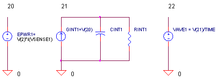
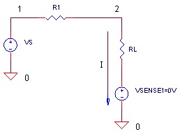
How do we use SPICE to the measure the power delivered to a load? Below shows a simple circuit with one additional element VSENSE1.
A voltage source in SPICE can measure the current in that branch. Just set it to 0V so there's no effect on circuit operation. Now simply use a Voltage Controlled Voltage Source (VCCS) to measure the instantaneous power.
EPWR1 20 0 VALUE = { V(2)*I(VSENSE1) }
CIRCUIT INSIGHT Simulate the POWER_METER.CIR circuit file.
DC LEVEL Voltage source VS (5 VDC) with series resistance R1 = 100 Ω drives the load RL = 100 Ω. Plot the input V(1) and the output V(2). How much power is delivered to the load? We can expect P = V x I = V2 / R = 2.5 V 2 / 100 Ω = 62.5 mW. What says your power meter at V(20)?
SINE WAVE What about the power for more complex waveforms like a sine wave? Replace the DC source with a sine wave by placing an "*" in front of the first VS statement and removing the "*" from the second VS statement. Run the simulation and plot the input
V(1), output V(2) and power V(20). Check out how the instantaneous power rises and falls with the shape of the sine wave. Vary the frequency and amplitude of the sine wave. Rerun the file and check out the power.QUESTION: What power level should you use when making calculations such as the heat generated or overall battery drain? Complex waveforms like sine waves have instantaneous power levels that very from 0 to high peak values.
ANSWER: Typically, the AVERAGE POWER is needed for these calculations.
AVERAGE POWER
How do you find the average power for a waveform that repeats every T seconds? Just reach into your bag of math tricks and pull out the averager.

Our SPICE averager falls right out of the above equation. Integrate the instantaneous power over one cycle and divide by T.
* INSTANTANEOUS POWER
EPWR1 20 0 VALUE = { V(2)*I(VSENSE1) }
* AVERAGE POWER
GINT1 0 21 VALUE = { V(20) }
CINT1 21 0 1 IC=0
RINT1 21 0 1MEG
EAVE1 22 0 VALUE = { V(21)/(TIME) }
How can you integrate using SPICE? Typically, you convert your node of interest V(20) into a current (GINT1) and then integrate it on a capacitor CINT1. Dummy resistor RINT1 provides some conductivity to ground to prevent SPICE from complaining about nodes with no DC path to ground. Finally, EAVE1 divides your integral by T to complete the equation. (Although SPICE displays V(22) as a voltage, we know it really represents power in Watts.)
CIRCUIT INSIGHT Again, simulate the POWER_METER.CIR file. To find the average of 10 kHz sine wave, we need to integrate over one complete 100 μs cycle.
SINE WAVE Plot V(1), V(2), the instantaneous power V(20) and the average power V(22). However, be careful how you read Pave at V(22)! Keep in mind, Pave is valid only at 100 μs - after one complete cycle of the 10 kHz sine wave.
With V(2) = 5 Vpeak, what is the average power? The SPICE circuit measures 125 mW. Is that true? Let's calculate the power using sine wave basics:
Pave = ( V(2) peak ∙ 0.707 ) 2 / R2
= ( 5 Vpeak ∙ 0.707 ) 2 / 100 Ω
= 125 mW.Way Cool! Now that our power meter has gained some credibility, let's checkout another waveform.
PUSLE TRAIN Let's drive RL with a pulse train by uncommenting VS defined by the PULSE statement. This source generates a 20 V pulse of width = 25 μs and period = 100 μs (Duty Cycle = D = 25 μs / 100 μs = 0.25.) What's the power in RL? Remember, the integral ain't over till it's over. Read V(22) at 100 μs! You should see about 250 mW. Reality check:
Pave = V(2) 2 / RL ∙ D
= 10 V 2 / 100 Ω ∙ 0.25
= 250 mW.Extend the simulation time by changing the 100US to 200US in the .TRAN statement. What is V(22) at the end of 100 and 200 μs? It should be the same! Why? Because you've got a repeating waveform. The average will be the same after one or multiple cycles. Extend the simulation further and check Pave at multiples of 100 μs. Try changing the frequency or the duty cycle of the pulse train. Is the power what you expected?
SETTLING TIME
CIRCUIT INSIGHT Suppose you need to measure Pave, but, your circuit needs time to settle after power up! Let's simulate this by adding 2000 nF across RL. Remove the "*" before the C1 statement.
C1 2 0 2000NF
Extend the simulation to 1000 μs and rerun the file. Notice the output V(2) growing slowly as the circuit reaches steady state. Not surprising, the instantaneous power V(20) follows suit. What happens to your average power reading V(22)? Sure, it's average gets dragged down by the low-power at start up. At the end of 1000 μs the power reads 58 mW. Pave has probably been underestimated!
DELAYED AVERAGE POWER
Given that outputs can rise slowly or overshoot at power up, how can you delay the calculation of Pave?
HANDS-ON DESIGN For the circuit above, a delay of 500 μs would work fine. You can achieve this by clamping the current source GINT1 to 0 for the first 500 μs. How? Just multiply the current by 0 until 500 us and then multiply it by 1 for the rest of the simulation. To do this, first modify GINT1.
GINT1 0 21 VALUE = { V(20)*V(40) }
Note the addition of V(40). Then create a step function at V(40) that rises from 0 to 1 after 500 μs.
VDELAY 40 0 PWL(0US 0V 500US 0V 500.1US 1V 1000US 1V)
Finally, don't forget that your time integral starts at 500 μs, so the EAVE1 statement needs a slight modification.
EAVE1 22 0 VALUE = { V(21)/(TIME-500US) }
Rerun the simulation with this advanced delay function. Hey, check out the delayed power at V(20) and V(22)! As intended, the power is clamped to 0 until 500 μs. Measure Pave at 1000 μs. Compared to 58 mW measured previously, what is the new Pave?
HANDS-ON DESIGN Is the delay long enough for your circuit to settle? Try increasing the delay from 500 to 800 or 900 μs. Simply adjust the delay times in the VDELAY and EAVE1 statements. Rerun the file and measure Pave at 1000 us. Is the value any different from the delay of 500 μs? If not, then the first delay was a reasonable time to let your circuit settle.
Try increasing or decreasing the settling time of the circuit by changing C1. What delay is needed for an accurate power measurement?
SPICE FILE
Download the file or copy this netlist into a text file with the *.cir extension.
POWER_METER.CIR - MEASURE POWER TO LOAD
*
* INPUT VOLTAGE
VS	1	0	DC	5V
*VS	1	0	SIN(0V 10V 10KHZ)
*VS	1	0	PULSE(0V 20V 0 0.1US 0.1US 25US 100US)
R1	1	2	100
*C1	2	0	2000NF
*
* LOAD
RL	2	3	100
VSENSE1	3	0	DC	0V
*
*
* INSTANTANEOUS POWER
EPWR1	20	0	VALUE = { V(2)*I(VSENSE1) }
* AVERAGE POWER
GINT1	0	21	VALUE = { V(20) }
CINT1   21   0   1	IC=0
RINT1	21	0 1MEG
EAVE1   22   0   VALUE = { V(21)/(TIME) }
*
VDELAY	40	0	PWL(0US 0V  500US 0V  500.1US 1V  1000US 1V)

* ANALYSIS
.IC V(22)=0V
.TRAN 	1US  	100US  0US 1US UIC
*
* VIEW RESULTS
.PLOT	TRAN	V(1) V(2) V(20) V(22)
.PROBE
.END
© 2005 eCircuit Center