Open-Loop 2nd & 3rd Poles
CIRCUIT
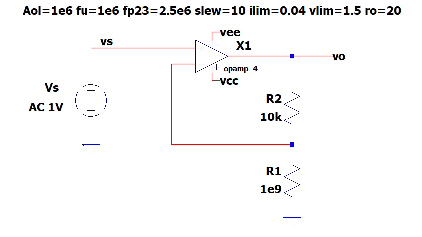
Schematic: Op_Amp_fp23.asc
Open Loop Sch: Op_Amp_fp23 - OL.asc
Op Amp Symbol: Opamp_4.asy
Op Amp Shematic: Opamp_4.asc
Right Click on filename, select "Save link as...",
Back to Design Series
SPEC IT
Intro Early on I was surprised to see some op amps would overshoot and ring, even with NO significant load or stray capacitance. What's going on here?
Although op amps have an internal on-purpose 1st pole (low-pass filter), most devices have several unwanted higher frequency poles due to parasitic capacitances of internal transistors. How do these affect your circuit? Additional poles cause Negative Phase-Shifts (Time-Delays) which push the op amp's control loop toward INSTABILITY!Definitions fp23 - The 2nd and 3rd pole frequencies.
• For convenience in the SPICE model, both poles are defined at the same frequency.
• Typically, the fp23 poles are located at 2 to 5 times above fu.
Unfortunately, you WON'T find the fp23 poles on the op amp datasheet. However, you'll see their impact on the Phase Margin - which you can read from the Open-Loop Gain plot (see below).Design Goal A stable amplifier output (minimial overshoot and ringing). Design Spec Overshoot < 10% given a 0.1V step voltage input.
DESIGN IT
- Circuit Design
- Signal Gain: Kcl = (R2+R1)/R1 = 1V/V
- Choose: R1=10k
- Calc: R2=Open (1e9)
- Op Model Param
- Aol=1e6 fu=1e6 fp23=2.5e6 slew=10 vlim=1.5 ilim=0.04 Ro=20
- Circuit Test
- Input: Vs = 0.1V voltage step
- Output: Vo = 0.1V
- Expected Overshoot < 10% or Vo < 110mV max.
TEST IT
- Run a Transient simulation. (.TRAN)
- Plot the output v(vo)
- Did it meet spec?
- If vo < 110mV, then PASS, else FAIL
- DESIGN ISSUE: The output fails to meet the overshoot design spec!
SOLVE IT
- Incrementally increase fp23 from 2e6 to 2.5e6, 3e6 and so on.
- Rerun the SPICE simulation after each increment.
- What value of fp23 is required to acheive the <10% design spec?
THEORY REFRESH
- Op amps have an intentional 1st pole (low-pass filter) plus several unwanted poles at higher frequencies.
- 1st Pole
- A low-pass response created with a capacitor in the Gain/Pole stage.
- fp1 is a relatively low freq pole designed to limit the overall device bandwidth to fu.
- 2nd and 3rd Poles
- Multiple poles created by parasitic capacitances internal to the op amp.
- fp2,3 are typically located at 2 to 5 times above fu.
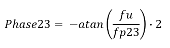
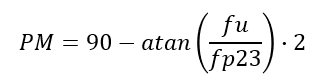
- You can approximate the added Negative Phase at the double pole fp23 by
- The Phase Margin tells you how close your circuit is to INSTABILITY!
- If PM = 0 deg, then you've got wild oscillations.
- If PM = 60 deg, then you've got a reasonable step response ~10% overshoot.
- Alternatively, we can ask what fp23 is needed for a specific PM?
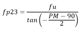
- Example: What fp23 is required to create a Phase Margin = 60 deg
with fu = 1e6?
fp23 = 1e6 / tan ( -(60-90)/2 ) = 3.7e6
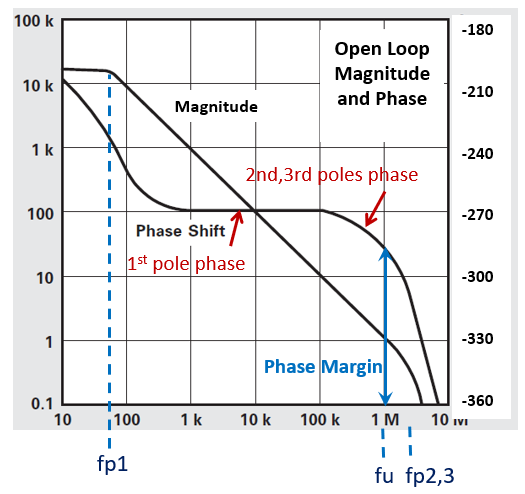
- Check out the Open-Loop Magnitude and Phase from a typical op amp's
datasheet.
- Real world Op Amps can have Phase Margins ranging from 40 to 60 deg causing
overshoots of 30 to 10% roughly for unity gain applications.
- So what happened to our original design?
- Open-Loop Analysis - Let's get some insight using this design power tool. Here's one approach
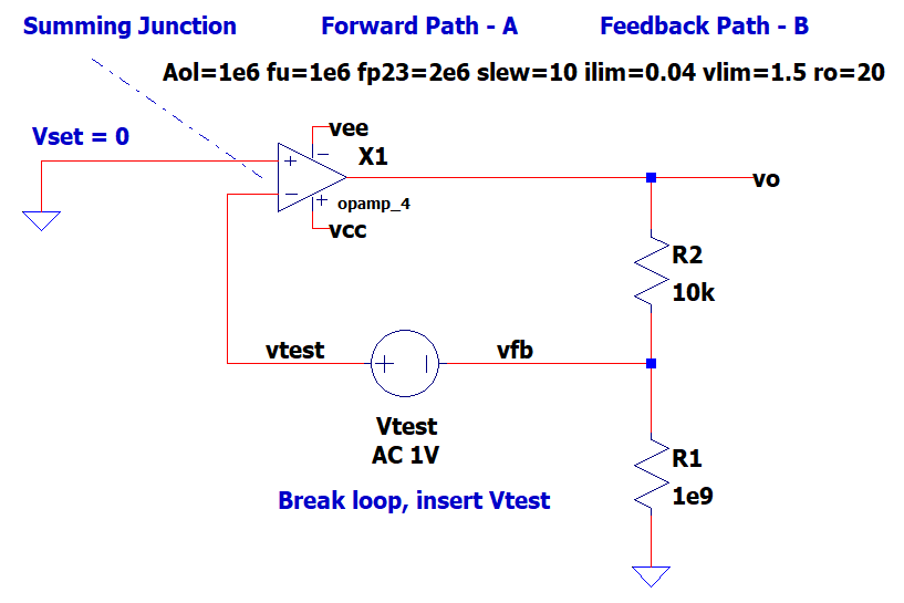
- Open-Loop Analysis in a nutshell.
- Set the signal source Vs = 0V.
- Break the loop open between R1,R2 divider node and op amp neg input.
- Insert Vtest into the opened loop.
Important impedance condition around Vtest: Z+ >> Z- - Run an AC analysis and plot the Magnitude and Phase around the Open Loop, v(vfb)/v(vtest).
- Check the Phase shift (time delay) where the Magnitide crosses 1V/V (or 0dB)
- Design Goal: Move Phase at 0dB more positively away from -360 (or +0) deg
for less overshoot and ringing.
Step Response Phase (deg) Oscillations - UNSTABLE -360 (or 0) 40% Overshoot -330 (or +30) 25% Overshoot -315 (or +45) 10% Overshoot -300 (or +60) No Overshoot - Optimal Response --270 (or +90)
- Discover fp23's impact on Phase using Open-Loop Analysis
- SPICE file: op_amp_fp23 - OL.asc
- NO higher poles: Run the AC sim with fp23 = 100e6 and plot v(vfb)/v(vtest).
- The Phase at 0dB (1V/V) should be close to -270 (or +90) deg, No overshoot.
- Add higher poles fp23: Run the AC sim with fp23 = 2e6 and plot v(vfb)/v(vtest).
- The Phase at 0dB (1V/V) should be close to -320 (or +40) deg, Unacceptable overshoot.
- Set fp23=3.7e6 for PM=60 deg as calculated above: Run the AC
sim and plot v(vfb)/v(vtest).
- The Phase at 0dB (1V/V) should be closer to -300 (or +60) deg. Acceptable overshoot.
- Retest the closed loop circuit op_amp_fp23.asc.
Did your circuit meet the overshoot spec? - Select a real-world op amp with a 60 deg Phase Margin from the device's Open-Loop Bode plot.
Back to Design Series...