Capacitance Measure
CIRCUIT
DMM_CAP_MEAS1.CIR
Download
the SPICE file
A quick search on "capacitance measurement" reaps a variety of intersting and clever methods. But the real challenge is choosing the method that takes advantage of your exisiting circuitry for other functions.
Folloowing the design of the Fluke meter, we see how the dual-slope integrator can be leveraged for the measurement of capacitance. Basically, the integrator will be used to find the total charge Q needed to bring the capacitor's potential up to a referelce voltage Vc.
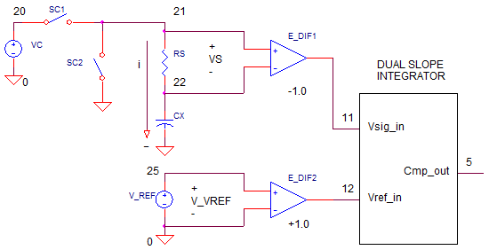
CAPACITANCE
The unknown capacitance (Rx) is defined by the charge Q accumulated on it's plates and the voltage Vc across it's terminals.
HOW MUCH CHARGE?
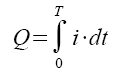
We can't measure the charge directly. However, we do know that integrating the current over time, gets us the total charge.
How do measure the instantasneous current? Notice there's a sense resistor Rs inseries with the C.
Vs = i · Rs.
THE METHOD
Basically, we'll charge up the capacitor to a reference voltage Vc and simultaneously measure how much charge it took to accomplish this. The capacitance is calculated as C = Q/Vc.
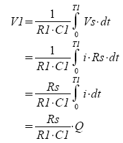
How is this performed? During T1, switch SC1 closes and the capacitor C charges to Vc. The voltage across the Rs is fed to the dual-slope integrator via S1. Notice the polarity of the diff amp is -1.0 such that -Vs feed the inverting integrator thereby developing a positive voltage at Vo.
During T2, the reference voltage Vref is fed to the integrator via S2 and the integrator ramps down to 0V. (Meanwhile the capacitor is discharged through SC2).
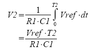
Because the integrator ramps up and down equally, you can set V1=V2. You'll immediately notice that the R1 and C1 terms cancel leaving you with
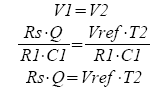
Solving for Q you get
Q = Vref ·T2 / Rs
The last piece of the method is calculating capacitance from charge.
C = Q/Vc = Vref ·T2 / (Rs·Vc)
Awesome sauce! In terms of the meter's reading, the interval T2 is propoertional to the measured capacitance.
T2 = (C·Rs·Vc) / Vref
MEASURE IT
We'll let the rubber meet the pavement with an example. Choosing Vc=10V, Vref=1V, Rs=1k and T2=10ms max, what is the full scale capacitance we can measure?
C = Q/Vc = (Vref ·T2) / (Rs·Vc) = (10V·10ms)/(1k·1V) = 1uF
This equation tells that the interval T2 (0 to 10ms) represents the measured capacoitance (0 to 1uF). Initially, set the unknown capacitance to CX=1uF.
voltage V(22), integrator output V(3) and comparator output V(5). Note
that the falling edge of V(5) at Tfall indicates the end of
T2.
= Tfall - 10ms
For CX=1uF ohms, where is the falling edge of V(5)? Uing the cursor, you find Tfall = 19.01ms which implies T1 = 20.003-10.0 = 10.003ms. The capacitance is easily calculated as
= T2 /10m · 1 uF
= 1.0003 uF
A reasonable measuremnt of capacitance!
Try entering another value of Cx. Rerun the simulation and check your result. What happens when the Cx gets too smalll? Try measureing Cx near 0.1 or 0.01 uF. How accurate is the measurement? Might be best to switch to lower range. What value of Rs is needed for these values? Did the accuracy improve?
DMM SERIES
Measure DC Volts with a Decade
Resistor Resistor Network.
Measure DC Current with a Decade
Current Sense Resistor Network.
Measure Resistance with a simple
modification of the Dual-Slope Integrator.
SPICE FILE
DVM_CAP_MEAS1.CIR
*
* CHARGE AND DISCHARGE C
VC	20	0	10VDC
SC1	20 21  15 0 SWB
SC2	21 0   15 0 SWA
*
* RS - CURRENT SENSE
RS	21	22	1000
*
* CX - UNKNOWN CAPACITOR
CX	22	0	1UF
*
* VREF
VREF	25	0	1VDC
*
* DIFF AMP - V REF
E_DIF2 12 0	25 0	+1.0
*
* DIFF AMP - RS
E_DIF1 11 0	21 22	-1.0
*
* CONTROL: VCNTRL=0 S1=ON, S2=OFF
*          VCNTRL=1 S1=Off,S2=ON
VCNTL	15	0	PWL(0MS 0V  10MS 0V 10.01MS 5V)
*
* INTEGRATOR
S1	11 1  15 0 SWB
S2	12 1  31 0 SWA
R1	1	2	100K
C1	2	3	0.10UF IC=0V
XOP1	0 2 3	OPAMP1
*
* COMPARATOR (ZERO CROSSING DETECTOR)
XCMP1	3 0 5 COMP1
*
* AND GATE, S2 = ON IF VCNTRL AND XCMP1 OUTPUTS ARE HI
VCC	30	0	DC	5V
R31	30	31	10k
D31 31	15	D1N4148
D32 31	5	D1N4148
*
*
* SUBCIRCUITS AND MODELS ***********************************
*
.SUBCKT COMP1  1 2 5
* TERMINALS: 1-INPUT+, 2-INPUT-, 5-OUTPUT
* DIFF AMP
EDIFF	3	0	VALUE = { V(1) - V(2) }
* FREQUENCY RESPONSE
RP1	3	4	500
CP1	4	0	1000PF
* LIMITER
EOUT	5	0	TABLE {V(4)} = (-0.5MV 0V) (0.5MV, 5V)
.ENDS
*
*
* OPAMP MACRO MODEL, SINGLE-POLE WITH 15V OUTPUT CLAMP
* connections:      non-inverting input
*                   |   inverting input
*                   |   |   output
*                   |   |   |
.SUBCKT OPAMP1	    1   2   6
* INPUT IMPEDANCE
RIN	1	2	10MEG
* DC GAIN=100K AND POLE1=100HZ
* UNITY GAIN = DCGAIN X POLE1 = 10MHZ
EGAIN	3 0	1 2	100K
RP1	3	4	100K
CP1	4	0	0.0159UF
* OUTPUT BUFFER AND RESISTANCE
EBUFFER	5 0	4 0	1
ROUT	5	6	10
.ENDS
*
.MODEL	SWA	VSWITCH(VON=5 VOFF=0 RON=1 ROFF=1e12)
.MODEL	SWB	VSWITCH(VON=0 VOFF=5 RON=1 ROFF=1e12)
*
* DIODE
.model	D1N4148	D(Is=0.1p Rs=16 CJO=2p Tt=12n Bv=100 Ibv=0.1p)
*
* ANALYSIS *************************************************
.TRAN 	25US  21MS UIC
*.TRAN 	0.1US  2000US UIC*
.PROBE
.END