Quick Intro to Op Amp Models
CIRCUIT

OP_NON.CIR Download the SPICE file
Op amp SPICE models vary in size from several to 100+
components. Why so many different SPICE models? That all depends if you're
looking to
simulate just the basic or the many subtle behaviors of an
op amp. If you're just getting your feet wet with op amps, the basic model
is all you need. It uses only a few components and typically simulates faster
than more complex ones (some models are so complex they can cause the SPICE
simulation to grind to a halt.)
THE BASIC MODEL
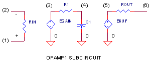
The basic behaviors are captured using three simple stages.
| Stage | Description | Netlist | |
| 1 | A differential amplifier with high voltage gain |
RIN 1 2 10MEG EGAIN 3 0 1 2 100K |
|
| 2 | A single-pole low-pass filter |
RP1 3 4 1K CP1 4 0 15.915UF |
|
| 3 | An output buffer with unity gain. |
EBUFFER 5 0 4 0 1 ROUT 5 6 10 |
There are only three connections to this op amp SPICE model: positive input - node 1, negative input - node 2 and output - node 3. No power supply connection needed in this basic model.
THE SUBCIRCUIT
The op amp model was created as a subcircuit named
OPAMP1. The subcircuit's netlist appears between the statements .SUBCKT
and .ENDS.
.SUBCKT OPAMP1 1 2 6
(netlist for subcircuit goes here.)
.ENDS
defined by three cponnection: 1 (in+), 2 (in-) and 4 (vout).
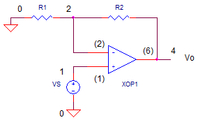
You can insert a subcircuits into another circuit using the "X" prefix for a component. For example, XOP1 calls subcircuit OPAMP1 into the netlist.
XOP1 1 2 4 OPAMP1
The XOP1 command will link main circuit nodes 1,2 and 4 with subcircuit nodes (1), (2) and (6), respectively. The node numbers of the subcircuit are independent of the main circuit. Even if the numbers are the same, SPICE renames them as separate numbers.
Why Subcircuits? They're handy in a couple of ways: 1) You can place a subcircuit (defined by you or someone else) into one or multiple locations of your main circuit. 2) You can maintain a clean and readable look to main circuit, keeping the subcircuit in another section of your file, or in another file altogether.
OP MODELS WITH POWER SUPPLY CONNECTIONS
Some models include power supply connections to simulate behaviors like output voltage limits. For example,
.SUBCKT OPAMP1 1 2 6 101 102
(netlist for subcircuit goes here.)
.ENDS
where nodes 101 (Vcc) and 102 (Vee) have been added.
BE AWARE! Various models different node orders. For example, you may see
.SUBCKT
OPAMP1 1 2 101 102 6
(netlist for subcircuit goes here.)
.ENDS
where the supply nodes appear in order before the output node 4. Simply verify that the node order in the subcircuit matches the oder in the main circuit!
THE TEST RUN
Let's take this model out on the road. Run a Transient Analysis (Time
domain) using the .TRAN statement. Voltage source VS drives the op amp's
input with 1V step input. The step function is created by a
Piece-Wise-Linear (PWL) command in the VS statement which defines the
waveform by a set of time-voltage pairs. With R1 = R2 = 10k, the gain should
be R2/R1+1 = 2 V/V.

CIRCUIT INSIGHT
Run a simulation and plot the input V(1) and output V(4).
Does the output reach the voltage predicted by the gain? How long does it
take to reach 90% of final value? Try increasing R2
to 20k or 30k. Rerun the simulation and check the output. Did the output increase?
Did it respond faster or slower with bigger gain? You'll find that the response
time is influenced by three factors: the internal DC Gain (EGAIN), the
low-pass filter (RP1,CP1) and the ratio of external resistors R2/R1.
RELATED TOPICS
Learn to create your own op amp model - The Basic Op Amp Model.
Explore all available op amp models - Op Amp Models.
Solve 10 Op Amp Design Issues using Custom LTSPICE MODELS.
SPICE FILE
Download the file
or copy this netlist into a text file with the *.cir
extention.
OPNON.CIR - OPAMP NON-INVERTING AMPLIFIER
*
VS	1	0	AC 1 PWL(0US 0V  0.1US 1V)
*
R1	2	0	10K
R2	2	4	10K
XOP	1 2	4	OPAMP1
*
* OPAMP MACRO MODEL, SINGLE-POLE
* connections:      non-inverting input
*                   |   inverting input
*                   |   |   output
*                   |   |   |
.SUBCKT OPAMP1      1   2   6
* INPUT IMPEDANCE
RIN	1	2	10MEG
* DC GAIN (100K) AND POLE 1 (10HZ)
EGAIN	3 0	1 2	100K
RP1	3	4	1K
CP1	4	0	15.915UF
* OUTPUT BUFFER AND RESISTANCE
EBUFFER	5 0	4 0	1
ROUT	5	6	10
.ENDS
*
* ANALYSIS
.TRAN 	0.1US  10US
*.AC 	DEC 	5 1K 10MEG
*
* VIEW RESULTS
.PROBE
.END
2010 - 2025 eCircuit Center