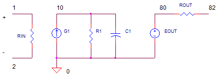
Slew-Rate Using LIMIT
CIRCUIT

IG1 = LIMIT( K1*V(1,2), IG1max+, IG1max-)
OP_SLEW_LIMIT.CIR Download the SPICE file
I'm amazed at how many different flavors of op amp SPICE models have been created. Each one built with its own philosophy, emphasizing one or more factors: performance, ease of use, understandability, compactness and/or convergence. None the least are the many paths to creating slew-rate behavior. The one discussed here seems to be the simplest to understand and easiest to calculate.
SLEW RATE
Slew-rate defines the maximum rate the op amp's output voltage can change. What defines this maximum? Inside the op amp, the input differential amplifier stage has a maximum current output, Iomax. During a big input voltage change, the diff amp gives up all its current into the compensation capacitor C which charges according to
V = Iomax · ∆T / C
The slew rate defines its max rate of voltage change over unit time
Slew Rate = ∆V / ∆T = Iomax / C1
In our SPICE model, Iomax will be represented by IG1max.
SPICE MODEL
With just three components - G1, R1 and C1 - you can model open-loop gain, bandwidth and slew rate. Here's an example netlist.
G1 0 10 VALUE={LIMIT( 2.5133e-2*V(1,2),0.01,-0.01)}
R1 10 0 1.592e+008
C1 10 0 0.0001uF
The key component is the the LIMIT function inside current source G1. The LIMIT syntax is simply
LIMIT( Output Expression, PosLimit, NegLimit)
For the Op Amp Model, we can fill in a few details concerning
transconductance gain
( K1 = IG1 / V(1,2) ) and the maximum output current IG1max.
LIMIT( K1*V(1,2), IG1max+, IG1max- )
How do calculate these components? First, choose G1's max current.
IG1max = 1 mA
Next, calculate C1 to achieve your slew rate.
C1 = IG1max / Slew
Now, find the location of the pole fp1 based on the op amp's unity gain frequency fu and the open loop gain Aol. Then, use C1 to calculate R1 to make it happen.
fp1 = fu / Aol
R1 = 1 /(2
·
pi
·
fp1
·
C1)
Finally, calculate G1's gain K1 to achieve the open loop gain Aol working into R1. To do this, first write the output voltage at V(10)
V(10) = IG1·R1 = K1·V(1,2)·R1.
Or write it as the open loop gain,
Aol = V(10) / V(1,2) = K1 · R1.
and then solve for K1.
K1 = Aol / R1
As an example, suppose you need to model an op amp with the following specs.
Open-Loop Gain 1,000,000 V/V
Unity Gain Bandwidth 10 MHz
Slew Rate 20 V/us
Let's crunch the numbers.
| Choose | IG1max = 0.001 | |
| Calculate |
C1 = I1 / Slew = 0.001 / 20e6 = 5e-11 |
|
|
fp1 = fu / Aol = 10e6 / 1e6 = 10 Hz |
||
|
R1 = 1/(2 * pi *
fp1 * C1) = 3.183e8 |
||
|
K1 = Aol /
R1 = 3.142e-3 |
EXCEL FILE
Here's an Excel file to help you calculate the SPICE model values. Op_Amp_Slew_LIMIT.xls.
ROAD TEST
Let's use the non-inverting amplifier to test drive our op amp SPICE model,

OPEN-LOOP AC RESPONSE To open the loop, remove R2 by placing a "*" in front of the R2 statement. R1 = 10 kΩ grounds the negative input.

Run an AC Analysis and plot the output V(3). How does the SPICE model perform? Does the open-loop response show a gain at low frequencies of Aol = 1e6 V/V? See if the gain falls to 0.707 of max amplitude at fp1 = 10 Hz. To get a better view, change the Y-Axis Settings to a log scale. And finally, does V(3) drop to unity at fu = 10 MHz? So far so good! Now let's check the slew rate.
CLOSED-LOOP RESPONSE Place R2 back into the circuit by removing the "*" at the beginning of the statement. VS generates a 5 V square wave. Run a Transient Analysis and plot the input V(1) and output V(3). With R1 = R2 = 10 kΩ, the non-inverting gain is 2 V/V. For a 5 V input, how fast does the output reach 10 V? For a slew-rate of 20 V/μs, you should get to 10 V in 0.5 μs.
CIRCUIT INSIGHT
During the slew-rate limited
interval, check the peak current from G1 by
plotting
I(XOP1.G1).
As advertised, it should max out at 1 mA. This is the max juice available to charge C1.
SIMULATION NOTES
Check out using the TANH function to model slew rate, see
Tanh Slew Rate.
For a description of all op amp models, see
Op Amp Models.
For a quick review of subcircuits, check out
Why Use Subcircuits?
Get a crash course on SPICE simulation at
SPICE Basics.
A handy reference is available at SPICE
Command Summary.
This op amp model can be used for many of the op amp
circuits available from the Circuit
Collection page.
SPICE FILES
Download the file or copy this netlist into a text file with the *.cir extension.
OPAMP_SLEW_LIMIT.CIR
*
* SIGNAL SOURCE
VS	1	0	AC 1	PWL(0US 0V   0.01US 5V  )

* NON INVERTING
R1	0	2	10K
R2	2	3	10K
XOP1	1	2 3 	OP_ILIMIT1
RL1	3	0	100K

*
* OP AMP MODEL - I LIMIT ***************************
*                       In+  In-  Vout
.SUBCKT OP_ILIMIT1	1    2    82
*
* INPUT R
RIN	1	2	1000MEG
*
*  INPUT STAGE: GAIN, POLE, SLEW
G1	0	10	VALUE = {  LIMIT( 3.142e-3*V(1,2), 0.001, -0.001) }
R1	10	0	3.183e8
C1	10	0	0.00005uF
*
* OUTPUT STAGE
EOUT	80 0	10 0	1
ROUT	80	82	10
.ENDS
*
* ANALYSIS *************************************
*
.TRAN 	0.05US  5US 0 0.025US
*.AC 	DEC 	20 0.1 1000MEG
.PROBE
.END
© 2009 eCircuit Center