I-to-V Amp with Offset
CIRCUIT
OPITOV_OFF.CIR Download the SPICE file
A common application of the I-to-V Amplifier is converting the current output of a DAC to a voltage. The DAC typically outputs a uni-polar current, say 0 to 2 mA. However, often you need to create a bipolar output of say +/-10V. How is this accomplished? A simple modification gets you there - simply add an offset to the output.
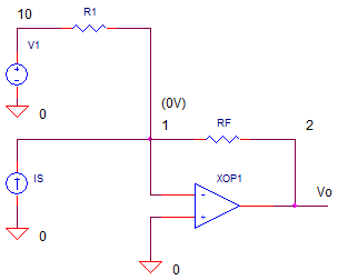
TRANS-IMPEDANCE AMP WITH OFFSET
This amplifier acts similar to the summing amp. The currents from both Is and R1 flow through RF creating a total current of Itot = Is + IR1. Because the op amp operation holds node 1 at 0V, the current flows through RF creating a negative output voltage
Vo = - Itot·RF
= - ( Is + IR1 ) ·RF
Substituting the current through R1 as IR1 = V1 / R1, we get
Vo = - (Is + V1/R1 ) ·RF
Rewriting slightly we arrive at
Vo = -Is·RF - V1·RF/R1
What's nice about this equation? You can easily set gain from Is and V1 to create any signal level and offset level you need.
DAC DRIVER
Suppose you have a 12-bit DAC (Digital to Analog Converter) that generates a uni-polar output of 0 to -1 mA for digital words 0 to 4095. However, the application calls for a bipolar output of -5 to +5 V. To achieve this, set RF=10k. The output will swing 0 to +10V for the input current of 0 to -1 mA multiplied by -RF. However, we need to shift this swing down by -5V to get the desired -5 to +5 V. The offset of -5V is accomplished by V1=5V multiplied by -RF/R1 = -1.
Vo = - Is·RF - V1·RF/R1
= -(0mA to -1mA)·(10k) - 5V·(10k/10k)
= (0V to +10V) - 5V
= -5V to +5V
CIRCUIT ANALYSIS Current source IS simulates a DAC output of 0 to -1 mA over 10ms. Run a simulation of OPITOV_OFFSET.CIR and plot the input current I(IS). In another window, plot the output voltage V(2). Does V(2) swing -5V to +5V as expected?
HANDS-ON DESIGN Suppose you needed to double the output voltage swing to +/-10V? This is the voltage range used by many motor control systems. Simply double RF from 10k to 20k. Run a simulation and check out V(2). Does it swing a total of 20V as desired. But what about the offset? You may need to adjust R1. For a 20V swing, you need to offset the output by -10V. With V1=5V and RF=20k, what value of R1 achieves the -10V offset? Change R1 and check the output swing.
WARNING - INSTABILITY AHEAD
The implementation of the trans-impedance amplifier is fraught with danger. Even a small stray capacitance can make the output overshoot and ring. Check out the topic on trans-impedance amp stability.
SPICE FILE
Download the file or copy this netlist into a text file with the *.cir extention.
OPITOV_OFFSET.CIR - CURRENT-TO-VOLTAGE CONVERTER (TRANSIMPEDANCE AMP)
*
* INPUT CURRENT
IS	0	1	AC	1	PWL(0US 0MA  100US -1MA)
*
* OFFSET VOLTAGE
V1	10	0	DC	5VDC
R1	10	1	10K
*
* TRANSIMPEDANCE AMPLIFIER
RF	1	2	10K
XOP1	0 1	2	OPAMP1
*
* OPAMP MACRO MODEL, SINGLE-POLE
* connections:      non-inverting input
*                   |   inverting input
*                   |   |   output
*                   |   |   |
.SUBCKT OPAMP1      1   2   6
* INPUT IMPEDANCE
RIN	1	2	10MEG
* gain bandwidth product = DCGAIN x POLE1 = 10MHZ
* DCGAIN=100K AND POLE1=100HZ
EGAIN	3 0	1 2	100K
R1	3	4	1K
C1	4	0	1.5915UF
* OUTPUT BUFFER AND RESISTANCE
EBUFFER	5 0	4 0	1
ROUT	5	6	10
.ENDS
*
* ANALYSIS
.TRAN 	0.2US  	100US
.PROBE
.END
© 2010 eCircuit Center